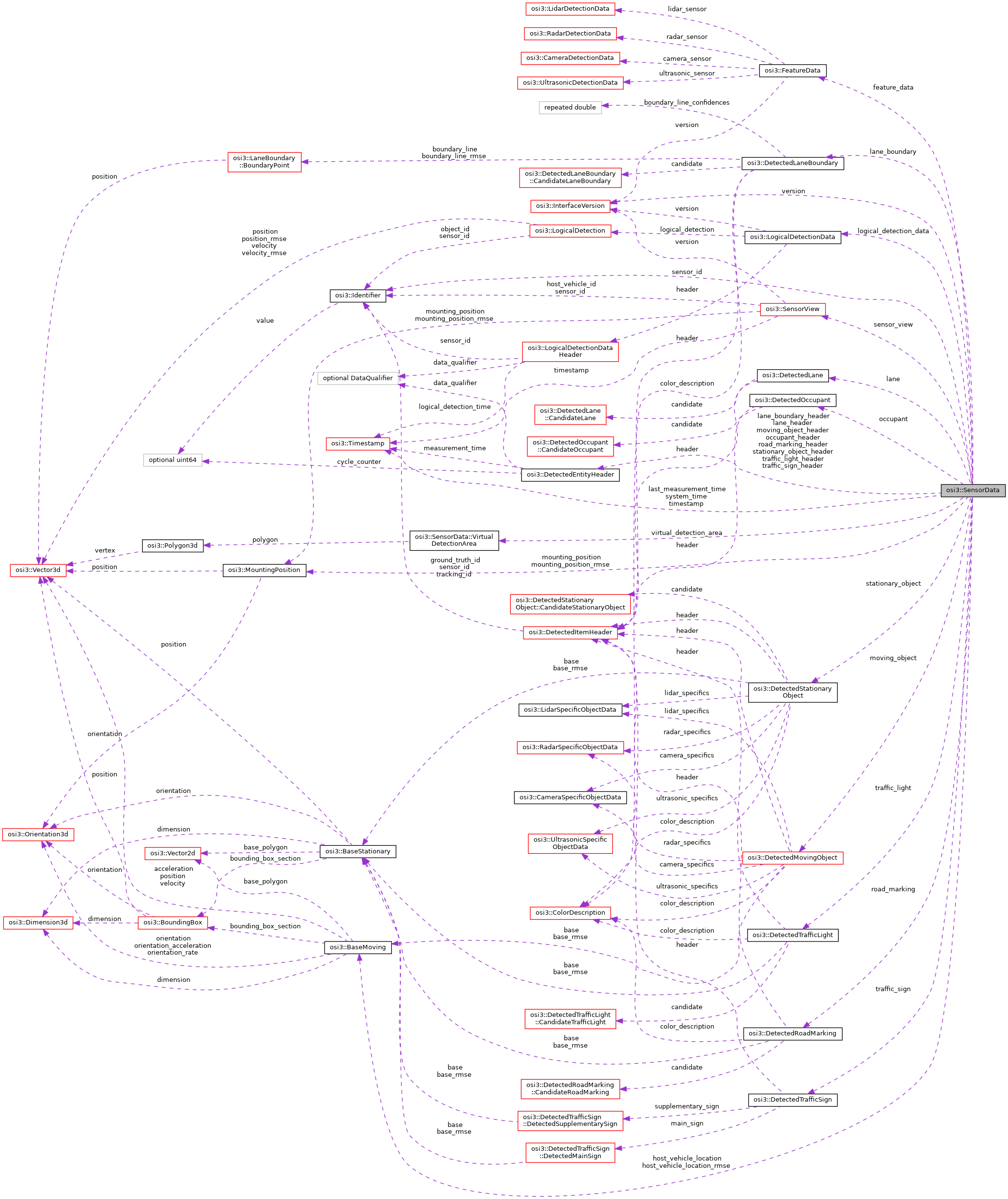
The sensor information derived from GroundTruth and processed by sensor-models.
More...
Classes | |
| struct | VirtualDetectionArea |
| Virtual detection area of a sensor. More... | |
Public Attributes | |
| optional InterfaceVersion | version = 1 |
| The interface version used by the sender. More... | |
| optional Timestamp | timestamp = 2 |
| The timestamp of the sensor data. More... | |
| optional BaseMoving | host_vehicle_location = 3 |
| The sensors estimated location of the host vehicle. More... | |
| optional BaseMoving | host_vehicle_location_rmse = 4 |
| The sensors estimated location error of the host vehicle. More... | |
| optional Identifier | sensor_id = 5 |
| The ID of the sensor at host vehicle's mounting_position. More... | |
| optional MountingPosition | mounting_position = 6 |
| The virtual mounting position of the sensor (origin and orientation of the sensor coordinate system) given in vehicle coordinates [1]. More... | |
| optional MountingPosition | mounting_position_rmse = 7 |
| The root mean squared error of the mounting position. More... | |
| repeated SensorView | sensor_view = 8 |
| Sensor view w.r.t. More... | |
| optional Timestamp | last_measurement_time = 9 |
| The timestamp of the last real-world measurement (e.g. More... | |
| optional DetectedEntityHeader | stationary_object_header = 10 |
General information about the DetectedStationaryObject . More... | |
| repeated DetectedStationaryObject | stationary_object = 11 |
| The list of stationary objects (e.g. More... | |
| optional DetectedEntityHeader | moving_object_header = 12 |
General information about the DetectedMovingObject . More... | |
| repeated DetectedMovingObject | moving_object = 13 |
| The list of moving objects detected by the sensor as perceived by the sensor. More... | |
| optional DetectedEntityHeader | traffic_sign_header = 14 |
General information about the DetectedTrafficSign . More... | |
| repeated DetectedTrafficSign | traffic_sign = 15 |
| The list of traffic signs detected by the sensor. More... | |
| optional DetectedEntityHeader | traffic_light_header = 16 |
General information about the DetectedTrafficLight . More... | |
| repeated DetectedTrafficLight | traffic_light = 17 |
| The list of traffic lights detected by the sensor. More... | |
| optional DetectedEntityHeader | road_marking_header = 18 |
General information about the DetectedRoadMarking . More... | |
| repeated DetectedRoadMarking | road_marking = 19 |
| The list of road markings detected by the sensor. More... | |
| optional DetectedEntityHeader | lane_boundary_header = 20 |
General information about the DetectedLaneBoundary . More... | |
| repeated DetectedLaneBoundary | lane_boundary = 21 |
| The list of lane boundary markings detected by the sensor. More... | |
| optional DetectedEntityHeader | lane_header = 22 |
General information about the DetectedLane . More... | |
| repeated DetectedLane | lane = 23 |
| The list of lanes detected by the sensor. More... | |
| optional DetectedEntityHeader | occupant_header = 24 |
General information about the DetectedOccupant . More... | |
| repeated DetectedOccupant | occupant = 25 |
| The list of occupants of the host vehicle. More... | |
| optional FeatureData | feature_data = 26 |
| Low level feature data interface. More... | |
| optional LogicalDetectionData | logical_detection_data = 27 |
| Logical detection data interface. More... | |
| optional VirtualDetectionArea | virtual_detection_area = 28 |
| Virtual detection area of the sensor. More... | |
| optional Timestamp | system_time = 29 |
| The system time of the modeled source of the sensor data, given in UTC (Unix Epoch timestamp). More... | |
Detailed Description
The sensor information derived from GroundTruth and processed by sensor-models.
The sensor information is supposed to imitate the output of real sensors. All information regarding the environment is given with respect to the virtual sensor coordinate system specified in SensorData::mounting_position, except for feature data, which is given with respect to the physical sensor coordinate system specified in the corresponding physical sensor's coordinate system.
When simulating multiple distinct sensors, each sensor can produce an individual copy of the SensorData interface. This allows an independent treatment of the sensors.
Sensor fusion models can consolidate multiple SensorData interfaces into one consolidated SensorData interface. This can happen either in separate logical models, consuming and producing SensorData interfaces, or it can happen as part of a combined sensor/logical model, that consumes SensorView interfaces and directly produces one consolidated SensorData output.
Member Data Documentation
◆ version
| optional InterfaceVersion osi3::SensorData::version = 1 |
The interface version used by the sender.
- Rules\n\code{.unparsed}
- is_set
◆ timestamp
| optional Timestamp osi3::SensorData::timestamp = 2 |
The timestamp of the sensor data.
Zero time is arbitrary but must be identical for all messages. Zero time does not need to coincide with the unix epoch. Recommended is the starting time point of the simulation.
- Note
- This is the point in time that the sensor data message becomes available to the rest of the system (i.e. the driving functions), so it corresponds with the sending time and thus takes the latency of internal processing of the sensor into account. Latencies of bus communications, etc., that occur after the sensor output have to be applied on top of this, if needed.
The time that the actual measurement was performed (which will usually correspond with the timestamp of the GroundTruth the sensor model processed to arrive at these results) can be found in the additional field SensorData::last_measurement_time.
For an ideal zero latency sensor the two timestamps would be the same and would correspond with the timestamp from the current GroundTruth message.
For a sensor model that does not know its own internal latencies (e.g. a dumb sensor with no internal time concept), the two timestamps might also be identical, but delayed from the GroundTruth timestamp.
- Rules\n\code{.unparsed}
- is_set
◆ host_vehicle_location
| optional BaseMoving osi3::SensorData::host_vehicle_location = 3 |
The sensors estimated location of the host vehicle.
- Note
- This value is only set by sensors that are able to provide an own estimation of the host vehicle location.
- Note that dimension and base_polygon need not be set.
-
The parent frame of
host_vehicle_locationis the sensor frame.
◆ host_vehicle_location_rmse
| optional BaseMoving osi3::SensorData::host_vehicle_location_rmse = 4 |
The sensors estimated location error of the host vehicle.
- Note
- This value is only set by sensors that are able to provide an own estimation of the host vehicle location.
- Note that dimension and base_polygon need not be set.
-
The parent frame of
host_vehicle_location_rmseis the sensor frame.
◆ sensor_id
| optional Identifier osi3::SensorData::sensor_id = 5 |
The ID of the sensor at host vehicle's mounting_position.
This is the ID of the virtual sensor, to be used in its detected object output; it is distinct from the IDs of its physical detectors, which are used in the detected features.
- Rules\n\code{.unparsed}
- is_set
◆ mounting_position
| optional MountingPosition osi3::SensorData::mounting_position = 6 |
The virtual mounting position of the sensor (origin and orientation of the sensor coordinate system) given in vehicle coordinates [1].
The virtual position pertains to the sensor as a whole, regardless of the actual position of individual physical detectors, and governs the sensor-relative coordinates in detected objects of the sensor as a whole. Individual features detected by individual physical detectors are governed by the actual physical mounting positions of the detectors, as indicated in the technology-specific sub-views and sub-view configurations.
- x-direction of sensor coordinate system: sensor viewing direction
- z-direction of sensor coordinate system: sensor (up)
- y-direction of sensor coordinate system: perpendicular to x and z right hand system
- Reference:
- [1] DIN Deutsches Institut fuer Normung e. V. (2013). DIN ISO 8855 Strassenfahrzeuge - Fahrzeugdynamik und Fahrverhalten - Begriffe. (DIN ISO 8855:2013-11). Berlin, Germany.
- Note
- This field is usually static during the simulation.
-
The origin of vehicle's coordinate system in world frame is (
MovingObject::base.BaseMoving::position+ Inverse_Rotation_yaw_pitch_roll(MovingObject::base.BaseMoving::orientation) *MovingObject::VehicleAttributes::bbcenter_to_rear) . The orientation of the vehicle's coordinate system is equal to the orientation of the vehicle's bounding boxMovingObject::base.BaseMoving::orientation.
- Rules\n\code{.unparsed}
- is_set
◆ mounting_position_rmse
| optional MountingPosition osi3::SensorData::mounting_position_rmse = 7 |
The root mean squared error of the mounting position.
◆ sensor_view
| repeated SensorView osi3::SensorData::sensor_view = 8 |
Sensor view w.r.t.
the sensor coordinate system
This provides a copy of the SensorView data received by the sensor for reference purposes. For complex sensors or logic models this can be multiple copies.
◆ last_measurement_time
| optional Timestamp osi3::SensorData::last_measurement_time = 9 |
The timestamp of the last real-world measurement (e.g.
GT input) that this set of sensor data takes into account. This in effect is the last time instance of reality the measurements correspond to. See field SensorData::timestamp for a detailed discussion. This value is also the upper bound to the DetectedEntityHeader::measurement_time and the feature data SensorDetectionHeader::measurement_time fields.
◆ stationary_object_header
| optional DetectedEntityHeader osi3::SensorData::stationary_object_header = 10 |
General information about the DetectedStationaryObject .
◆ stationary_object
| repeated DetectedStationaryObject osi3::SensorData::stationary_object = 11 |
The list of stationary objects (e.g.
landmarks) detected by the sensor.
◆ moving_object_header
| optional DetectedEntityHeader osi3::SensorData::moving_object_header = 12 |
General information about the DetectedMovingObject .
◆ moving_object
| repeated DetectedMovingObject osi3::SensorData::moving_object = 13 |
The list of moving objects detected by the sensor as perceived by the sensor.
◆ traffic_sign_header
| optional DetectedEntityHeader osi3::SensorData::traffic_sign_header = 14 |
General information about the DetectedTrafficSign .
◆ traffic_sign
| repeated DetectedTrafficSign osi3::SensorData::traffic_sign = 15 |
The list of traffic signs detected by the sensor.
◆ traffic_light_header
| optional DetectedEntityHeader osi3::SensorData::traffic_light_header = 16 |
General information about the DetectedTrafficLight .
◆ traffic_light
| repeated DetectedTrafficLight osi3::SensorData::traffic_light = 17 |
The list of traffic lights detected by the sensor.
◆ road_marking_header
| optional DetectedEntityHeader osi3::SensorData::road_marking_header = 18 |
General information about the DetectedRoadMarking .
◆ road_marking
| repeated DetectedRoadMarking osi3::SensorData::road_marking = 19 |
The list of road markings detected by the sensor.
This excludes lane boundary markings.
◆ lane_boundary_header
| optional DetectedEntityHeader osi3::SensorData::lane_boundary_header = 20 |
General information about the DetectedLaneBoundary .
◆ lane_boundary
| repeated DetectedLaneBoundary osi3::SensorData::lane_boundary = 21 |
The list of lane boundary markings detected by the sensor.
◆ lane_header
| optional DetectedEntityHeader osi3::SensorData::lane_header = 22 |
General information about the DetectedLane .
◆ lane
| repeated DetectedLane osi3::SensorData::lane = 23 |
The list of lanes detected by the sensor.
◆ occupant_header
| optional DetectedEntityHeader osi3::SensorData::occupant_header = 24 |
General information about the DetectedOccupant .
◆ occupant
| repeated DetectedOccupant osi3::SensorData::occupant = 25 |
The list of occupants of the host vehicle.
◆ feature_data
| optional FeatureData osi3::SensorData::feature_data = 26 |
Low level feature data interface.
Low Level feature data is optionally provided by sensor models that model sensors giving access to this low level data, i.e. data prior to object hypothesis and tracking.
◆ logical_detection_data
| optional LogicalDetectionData osi3::SensorData::logical_detection_data = 27 |
Logical detection data interface.
Logical detection data are provided by a transformation (and optional sensor fusion) performed by a sensor model or a logical model that fuses multiple sensors and/or sensor types into a single reference frame of the so called logical/virtual sensor. Therefore, all information is given with respect to the reference frame of the logical/virtual sensor SensorView::mounting_position (e.g. center of rear axle of the ego car) in cartesian coordinates.
◆ virtual_detection_area
| optional VirtualDetectionArea osi3::SensorData::virtual_detection_area = 28 |
Virtual detection area of the sensor.
◆ system_time
| optional Timestamp osi3::SensorData::system_time = 29 |
The system time of the modeled source of the sensor data, given in UTC (Unix Epoch timestamp).
The system time can be used to transmit the internal time of the simulated component that supplies the sensor data, which might not coincide with the simulation time as transmitted in the timestamp field. Example use cases include recorded data traces or the simulation of time synchronization mechanisms and errors.
The documentation for this struct was generated from the following file:
- osi_sensordata.proto