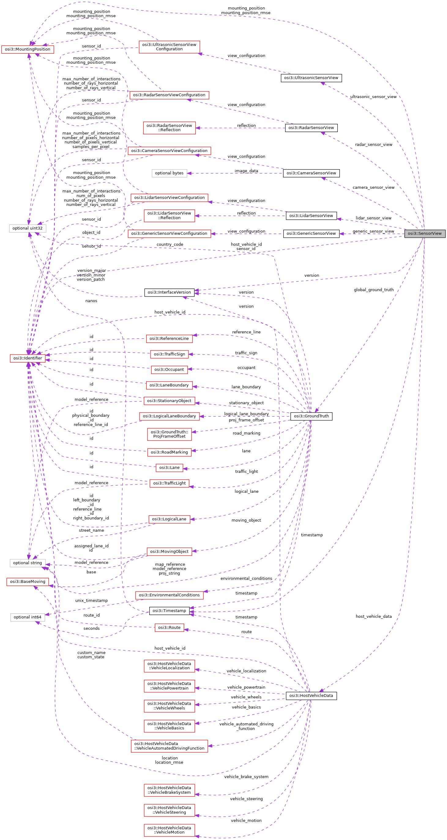
The sensor view is derived from GroundTruth and used as input to sensor models.
More...
Public Attributes | |
| optional InterfaceVersion | version = 1 |
| The interface version used by the sender (simulation environment). More... | |
| optional Timestamp | timestamp = 2 |
| The data timestamp of the simulation environment. More... | |
| optional Identifier | sensor_id = 3 |
The ID of the sensor at host vehicle's mounting_position. More... | |
| optional MountingPosition | mounting_position = 4 |
| The virtual mounting position of the sensor (origin and orientation of the sensor frame). More... | |
| optional MountingPosition | mounting_position_rmse = 5 |
| The root mean squared error of the mounting position. More... | |
| optional HostVehicleData | host_vehicle_data = 6 |
| Host vehicle data. More... | |
| optional GroundTruth | global_ground_truth = 7 |
| Ground truth w.r.t. More... | |
| optional Identifier | host_vehicle_id = 8 |
The ID of the host vehicle in the global_ground_truth data. More... | |
| repeated GenericSensorView | generic_sensor_view = 1000 |
| Generic SensorView(s). More... | |
| repeated RadarSensorView | radar_sensor_view = 1001 |
| Radar-specific SensorView(s). More... | |
| repeated LidarSensorView | lidar_sensor_view = 1002 |
| Lidar-specific SensorView(s). More... | |
| repeated CameraSensorView | camera_sensor_view = 1003 |
| Camera-specific SensorView(s). More... | |
| repeated UltrasonicSensorView | ultrasonic_sensor_view = 1004 |
| Ultrasonic-specific SensorView(s). More... | |
Detailed Description
The sensor view is derived from GroundTruth and used as input to sensor models.
The sensor view information is supposed to provide input to sensor models for simulation of actual real sensors. All information regarding the environment is given with respect to the virtual sensor coordinate system specified in SensorView::mounting_position, except for the individual physical technology-specific data, which is given with respect to the physical sensor coordinate system specified in the corresponding physical sensor's mounting_position, and the global_ground_truth, which is given in global coordinates.
When simulating multiple distinct sensors, each sensor can consume an individual copy of the SensorView interface. This allows an independent treatment of the sensors.
Alternatively combined sensor models can also consume one combined SensorView, with either combined or separate SensorData outputs, depending on model architecture.
Member Data Documentation
◆ version
| optional InterfaceVersion osi3::SensorView::version = 1 |
The interface version used by the sender (simulation environment).
- Rules\n\code{.unparsed}
- is_set
◆ timestamp
| optional Timestamp osi3::SensorView::timestamp = 2 |
The data timestamp of the simulation environment.
Zero time is arbitrary but must be identical for all messages. Zero time does not need to coincide with the UNIX epoch. Recommended is the starting time point of the simulation.
- Note
- For sensor view data this timestamp coincides both with the notional simulation time the data applies to and the time it was sent (there is no inherent latency for sensor view data, as opposed to sensor data).
- Rules\n\code{.unparsed}
- is_set
◆ sensor_id
| optional Identifier osi3::SensorView::sensor_id = 3 |
The ID of the sensor at host vehicle's mounting_position.
This is the ID of the virtual sensor, to be used in its detected object output; it is distinct from the IDs of its physical detectors, which are used in the detected features.
- Rules\n\code{.unparsed}
- is_globally_unique is_set
◆ mounting_position
| optional MountingPosition osi3::SensorView::mounting_position = 4 |
The virtual mounting position of the sensor (origin and orientation of the sensor frame).
Both origin and orientation are given in and with respect to the host vehicle coordinate system [1].
The virtual position pertains to the sensor as a whole, regardless of the actual position of individual physical detectors, and governs the sensor-relative coordinates in detected objects of the sensor as a whole. Individual features detected by individual physical detectors are governed by the actual physical mounting positions of the detectors, as indicated in the technology-specific sub-views and sub-view configurations.
- x-direction of sensor coordinate system: sensor viewing direction
- z-direction of sensor coordinate system: sensor (up)
- y-direction of sensor coordinate system: perpendicular to x and z right hand system
- Reference:
- [1] DIN Deutsches Institut fuer Normung e. V. (2013). DIN ISO 8855 Strassenfahrzeuge - Fahrzeugdynamik und Fahrverhalten - Begriffe. (DIN ISO 8855:2013-11). Berlin, Germany.
- Note
- This field is usually static during the simulation.
-
The origin of vehicle's coordinate system in world frame is (
MovingObject::base.BaseMoving::position+ Inverse_Rotation_yaw_pitch_roll(MovingObject::base.BaseMoving::orientation) *MovingObject::VehicleAttributes::bbcenter_to_rear) . The orientation of the vehicle's coordinate system is equal to the orientation of the vehicle's bounding boxMovingObject::base.BaseMoving::orientation.
- Rules\n\code{.unparsed}
- is_set
◆ mounting_position_rmse
| optional MountingPosition osi3::SensorView::mounting_position_rmse = 5 |
The root mean squared error of the mounting position.
◆ host_vehicle_data
| optional HostVehicleData osi3::SensorView::host_vehicle_data = 6 |
Host vehicle data.
Host vehicle data is data that the host vehicle knows about itself, e.g. from location sensors, internal sensors and ECU bus data, etc., that is made available to sensors as input.
◆ global_ground_truth
| optional GroundTruth osi3::SensorView::global_ground_truth = 7 |
Ground truth w.r.t.
global coordinate system.
This is the ground truth that is provided to the sensor model by the simulation environment. It may be filtered as per the requirements of the sensor model as expressed by the SensorViewConfiguration message(s) that where exchanged during the simulation initialization phase.
- Note
- The host vehicle is always contained in the ground truth provided, regardless of any filtering. The ground truth MUST contain at least as much of the ground truth data, as is requested by the sensor model, but MAY always contain more data, since the filtering is intended only as an optimization mechanism, not as a replacement of a proper sensor field of view modeling.
◆ host_vehicle_id
| optional Identifier osi3::SensorView::host_vehicle_id = 8 |
The ID of the host vehicle in the global_ground_truth data.
- Rules\n\code{.unparsed}
- refers_to: 'MovingObject' is_set
◆ generic_sensor_view
| repeated GenericSensorView osi3::SensorView::generic_sensor_view = 1000 |
Generic SensorView(s).
◆ radar_sensor_view
| repeated RadarSensorView osi3::SensorView::radar_sensor_view = 1001 |
Radar-specific SensorView(s).
◆ lidar_sensor_view
| repeated LidarSensorView osi3::SensorView::lidar_sensor_view = 1002 |
Lidar-specific SensorView(s).
◆ camera_sensor_view
| repeated CameraSensorView osi3::SensorView::camera_sensor_view = 1003 |
Camera-specific SensorView(s).
◆ ultrasonic_sensor_view
| repeated UltrasonicSensorView osi3::SensorView::ultrasonic_sensor_view = 1004 |
Ultrasonic-specific SensorView(s).
The documentation for this struct was generated from the following file:
- osi_sensorview.proto