Boundary line of a LogicalLane. More...
Classes | |
| struct | LogicalBoundaryPoint |
| A point on the boundary. More... | |
Public Types | |
| enum | PassingRule { PASSING_RULE_UNKNOWN = 0 , PASSING_RULE_OTHER = 1 , PASSING_RULE_NONE_ALLOWED = 2 , PASSING_RULE_INCREASING_T = 3 , PASSING_RULE_DECREASING_T = 4 , PASSING_RULE_BOTH_ALLOWED = 5 } |
| Passing rule of the LogicalLaneBoundary. More... | |
Public Attributes | |
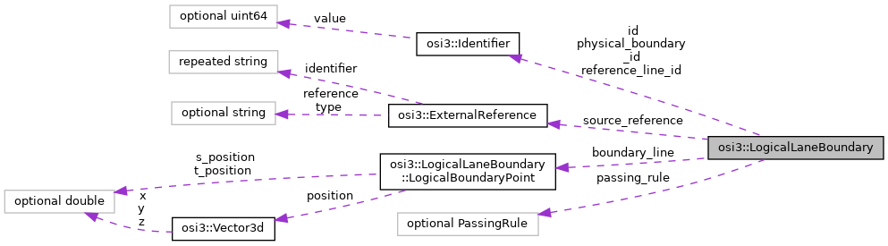
| optional Identifier | id = 1 |
| The ID of the lane boundary. More... | |
| repeated LogicalBoundaryPoint | boundary_line = 2 |
| Points making up the lane boundary. More... | |
| optional Identifier | reference_line_id = 3 |
| The reference line for this boundary. More... | |
| repeated Identifier | physical_boundary_id = 4 |
| Reference to the physical lane boundary or boundaries that make up this logical boundary. More... | |
| optional PassingRule | passing_rule = 5 |
| The passing rules, insomuch as they can be determined just from road markings. More... | |
| repeated ExternalReference | source_reference = 6 |
| Optional external reference to the lane boundary source. More... | |
Detailed Description
Boundary line of a LogicalLane.
Similar to a LaneBoundary, but with a reference line and ST positions.
A logical lane boundary describes the boundary between two logical lanes. As such, there will always be exactly one logical lane boundary between two lanes at a given S position. Contrary to that, there can be 0 to N physical lane boundaries (i.e. type LaneBoundary) between two logical lanes at a given S position.
If there are multiple physical lane boundaries at one S position between two lanes (think of a solid-broken marking, which would be described by two LaneBoundary objects, one for the solid lane marking, one for the broken lane marking), then the single LogicalLaneBoundary describing the boundary between two logical lanes should be between the physical boundaries.
A logical lane boundary consists of a list of LogicalBoundaryPoints. Each point has a XYZ and an ST coordinate. The XYZ coordinates describe the position and height of the boundary in the world.
Notes on design decisions:
- The LogicalLaneBoundary has ST coordinates, and is thus a separate type from LaneBoundary. Advantages of this decision:
- Calculations like getting the lane width at a position are easy, since one can just get the boundary points of the left and right boundary at the desired S position (via linear interpolation), and calculate the width from the two points. Also getting something like the distance to the lane border is very easy.
- No centerline of the lane is necessary, since this can very easily be generated from the boundaries. Disadvantages of this decision:
- Lane boundaries cannot be shared with physical lanes. This results in more data needed. This can mostly be mitigated by only transmitting the lane boundaries during initialization (e.g. via the OSMP GroundTruthInit message).
- The LogicalLaneBoundary contains all data directly which an agent model is likely to need. It does not include information normally only used by sensor models (e.g. the exact length of the color markings on the road). This information can be gotten from the physical lane referenced in the LogicalLane, if needed.
Member Enumeration Documentation
◆ PassingRule
Passing rule of the LogicalLaneBoundary.
This describes how vehicles are legally allowed to move across the LogicalLaneBoundary. The PassingRule is determined solely based on the semantics of (physical) lane boundaries, not on any signs (i.e. it may be overridden by signs).
| Enumerator | |
|---|---|
| PASSING_RULE_UNKNOWN | Passing rule is unknown (must not be used in ground truth). |
| PASSING_RULE_OTHER | Passing rule fits neither of the other categories. Example: this type needs to be used if passing depends on the agent type, e.g. if cars may change lane, but trucks may not. This value is also used between LogicalLanes where the traffic regulations do not say anything about passing rules (e.g. for a LogicalLaneBoundary between LogicalLanes of TYPE_NORMAL and TYPE_CURB or between LogicalLanes of TYPE_BORDER and TYPE_SHOULDER) . |
| PASSING_RULE_NONE_ALLOWED | No passing is allowed (neither from left to right nor from right to left). |
| PASSING_RULE_INCREASING_T | Only passing in increasing T direction allowed. Passing is allowed from one lane to the other if the points on the target lane have larger T values than points on the source lane (at the same S position). In reference line direction (but not necessarily in driving direction), this means changing from right to left is allowed. |
| PASSING_RULE_DECREASING_T | Only passing in decreasing T direction allowed. Passing is allowed from one lane to the other if the points on the target lane have smaller T values than points on the source lane (at the same S position). In reference line direction (but not necessarily in driving direction), this means changing from left to right is allowed. |
| PASSING_RULE_BOTH_ALLOWED | Passing is allowed in both directions (left to right and right to left). |
Member Data Documentation
◆ id
| optional Identifier osi3::LogicalLaneBoundary::id = 1 |
The ID of the lane boundary.
- Rules\n\code{.unparsed}
- is_globally_unique is_set
◆ boundary_line
| repeated LogicalBoundaryPoint osi3::LogicalLaneBoundary::boundary_line = 2 |
Points making up the lane boundary.
The boundary must be defined in the same direction as the reference line. So S positions should increase along the line. Note that S positions will not always increase strictly monotonically. Example:
               |---------\
               |          \
 /---boundary--|           \------------
/
---------- reference line --------------
At the place where the boundary suddenly increases, two points will have the same S coordinate.
If the boundary approximates a curve (e.g. a cubic function in OpenDRIVE), the points must be chosen in a way that the lateral distance to the ideal line does not exceed 5cm. As shown in the following image:
Approximation error green line.
The Z error (difference in Z height between boundary_line and the "real" line) must not exceed 2cm. This is a stricter requirement than for errors in the XY plane, because Z differences between lanes influence driving very much.
Note: if two lanes have different Z heights (e.g. a driving lane is beside a sidewalk, where the sidewalk is 10cm higher than the road), then these lanes cannot share a boundary, since their boundaries have different Z heights.
◆ reference_line_id
| optional Identifier osi3::LogicalLaneBoundary::reference_line_id = 3 |
The reference line for this boundary.
The reference line is used as a coordinate system for this boundary. All points of this LogicalLaneBoundary must have S coordinates in the range [sStart,sEnd].
The reference line should roughly have the same shape as the boundary (so roughly parallel to the lane middle), so that S coordinates continually increase along the boundary.
- Rules\n\code{.unparsed}
- refers_to: ReferenceLine
◆ physical_boundary_id
| repeated Identifier osi3::LogicalLaneBoundary::physical_boundary_id = 4 |
Reference to the physical lane boundary or boundaries that make up this logical boundary.
Rules and notes:
- This list is empty if there are no physical lane boundaries to delimit a lane.
- In the common case, this will contain one physical boundary.
- This list contains several lane boundaries if there are several physical lane boundaries at one S position (e.g. both a broken and a solid line).
- If there are several lane boundaries, they must be listed in increasing T order (i.e. from right to left in reference line direction). Rationale: this makes it easier to determine e.g. rules on lane changes, which depend on the T order of the lanes.
- Whenever physical lane boundaries begin or end, or switch their T position (if there are multiple physical lane boundaries), a new LogicalLaneBoundary must be created.
- The referenced LaneBoundary objects may be longer than the LogicalLaneBoundary which references them, but must never be shorter.
Example:
      Lane 1
 --------a------------------ - - - -c- - - -           ---->
 - - - -b- - - -
      Lane -1
This shows the boundary between lane 1 and lane -1, with the reference line going from left to right. First there is a solid-broken line (a and b), then there is only a solid line (a), then there is a broken line (c). There would be three LogicalLaneBoundary objects between Lane1 and Lane2: the first would reference first b and then a, the second would reference only a, and the third would reference c.
- Rules\n\code{.unparsed}
- refers_to: LaneBoundary
◆ passing_rule
| optional PassingRule osi3::LogicalLaneBoundary::passing_rule = 5 |
The passing rules, insomuch as they can be determined just from road markings.
◆ source_reference
| repeated ExternalReference osi3::LogicalLaneBoundary::source_reference = 6 |
Optional external reference to the lane boundary source.
- Note
- For OpenDRIVE, there is no direct possibility to reference the RoadMark, as there is no unique identifier in this sub-object.
- For non-ASAM Standards, it is implementation-specific how source_reference is resolved.
- The value has to be repeated because one object may be derived from more than one origin source, for example, from a scenario file and from sensors.
The documentation for this struct was generated from the following file:
- osi_logicallane.proto