A reference line for defining a non-Euclidean ST coordinate system. More...
Classes | |
| struct | ReferenceLinePoint |
| A point on the reference line. More... | |
Public Types | |
| enum | Type { TYPE_POLYLINE = 0 , TYPE_POLYLINE_WITH_T_AXIS = 1 } |
| ReferenceLine types. More... | |
Public Attributes | |
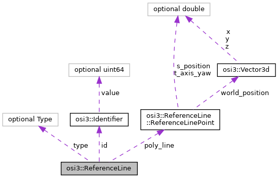
| optional Identifier | id = 1 |
| The ID of the reference line. More... | |
| optional Type | type = 3 |
| The type of the reference line. More... | |
| repeated ReferenceLinePoint | poly_line = 2 |
| Points comprising the polyline. More... | |
Detailed Description
A reference line for defining a non-Euclidean ST coordinate system.
A reference line is a 3D polyline, used for generating a non-Euclidean ST coordinate system.
- Note
- This ST coordinate system is specific to OSI and not to be confused with similar definitions in other standards like OpenDRIVE or OpenSCENARIO 1.x. Nevertheless the goal of this definition is to approximate the source coordinates (e.g. OpenDRIVE).
Notes on design decisions:
- This is a polyline, and not some more complex curve. The advantage of a polyline is that it is very simple to generate from various map formats, and it is also easy to handle. The downside is that a polyline has no direct curvature, and even the angle is not continuous (only C0 smooth). In the author's experience, the benefits of a polyline outweigh the costs.
Member Enumeration Documentation
◆ Type
ReferenceLine types.
ReferenceLinePoints might be interpreted differently depending on the type of the ReferenceLine.
See also: "Adding T coordinates"
| Enumerator | |
|---|---|
| TYPE_POLYLINE | ReferenceLine is a polyline, where the coordinates of points are calculated by projection onto the nearest point on the line.
|
| TYPE_POLYLINE_WITH_T_AXIS | ReferenceLine is a polyline, where the coordinates of points are calculated using the T axis definition.
|
Member Data Documentation
◆ id
| optional Identifier osi3::ReferenceLine::id = 1 |
The ID of the reference line.
- Note
- Note ID is global unique.
- Rules\n\code{.unparsed}
- is_globally_unique is_set
◆ type
| optional Type osi3::ReferenceLine::type = 3 |
The type of the reference line.
◆ poly_line
| repeated ReferenceLinePoint osi3::ReferenceLine::poly_line = 2 |
Points comprising the polyline.
At least two points must be given. The polyline is defined as the lines between consecutive points. Each point has an S coordinate. Other attributes might be set, depending on the type of the polyline (see Type).
Rules on the S position
There are a few requirements on the S position:
- Later points in the list must have strictly larger S coordinates than earlier points.
- For consecutive points, the S difference between them must be at least as large as the 2D Euclidean distance between the points (2D distance == Euclidean distance between the points taking only X and Y into account).
- The S distance between two points may be larger than the 2D Euclidean distance, but should be not much larger. It is allowed to be larger if the underlying reference line (e.g. in an OpenDRIVE map) is a curve, and thus the sampled reference line has a smaller length than the original curve.
Together, these rules allow directly putting OpenDRIVE S coordinates into an OSI ReferenceLine.
If the reference line approximates a curve (e.g. a clothoid in OpenDRIVE), the points must be chosen in a way that the lateral distance to the ideal line does not exceed 5cm. As shown in the following image:
Approximation error green line.
Between two ReferenceLinePoints, both the world coordinate and the S coordinate is interpolated linearly. So each S value uniquely describes a point on the polyline.
Extending the coordinate system infinitely
For the purpose of this discussion, let's call the S position of the first point sStart, and the S position of the last point sEnd.
For some purposes, S positions outside the normally defined range (i.e. outside [sStart,sEnd]) need to be defined. For this purpose, the first line of the polyline is infinitely extended in negative S direction. Similarly, the last line of the polyline is infinitely extended beyond the last point. The S value of points outside [sStart,sEnd] is defined by the Euclidean 2D distance from the start or end point, respectively. So if sStart = 15, and a point is on the line extended from the start position, with a 2D Euclidean distance of 10 from the first point, then it has an S position of 5.
A point is "before" the reference line, if its s coordinate is < sStart. A point is "after" the reference line, if its s coordinate is > sEnd.
Adding T coordinates
To describe points that are not directly on the polyline, a T coordinate is added. T is the signed 2D distance between the point to describe (P) and a projected point (P_proj) on the polyline. There are two ways of defining this point, depending on the ReferenceLine::Type (see below).
The T coordinate of the point in question is then defined as hypot(P.X-P_proj.X,P.Y-P_proj.Y). The projected point P_proj might either be on a line segment or at an edge between two line segments. The distance is positive if the point is left of the polyline (in definition direction), negative if it is right of it. The S position of such a point outside the reference line is the same as the S value of the projected point on the polyline.
Nearest point (TYPE_POLYLINE)
The projection point is the nearest point on the polyline (this point might either be on a line segment or at an edge between two line segments).
Notes:
- The "nearest point on the polyline" is determined in 3D (even if the resulting T value is only the 2D distance), in order to choose the correct point for 3D curves (think reference lines for roads in parking decks).
- If there are several "nearest points", the one with the smallest S coordinate on the polyline is chosen.
Example:
This shows a reference line (consisting of three points), and five points not on the reference line.
- For
P1, the situation is clear, since there is exactly one nearest point on the polyline. The resulting ST coordinate uniquely maps back toP1. P2has multiple points "nearest points" on the polyline. As can be seen here, two ST coordinates map toP2(red and gray dotted line). Following the rules above, the one with the smallest S value is chosen (the red dotted line).P3has a unique "nearest point" on the polyline. However, multiple points map to the same ST coordinate as that ofP3, e.g.P4(drawn in gray).- Finally,
P5shows how the reference line is extended infinitely for points that are "outside" the reference line.
T axis definition (TYPE_POLYLINE_WITH_T_AXIS)
The T axes of the two ReferenceLinePoints of each ReferenceLine segment define a sector (or strip if parallel) of the plane. A point is associated with the segment if it lies within this sector. For points being associated with multiple segments, the actual segment to consider is determined by the shortest 3D Euclidean distance between the point and the segments in question.
The T axis (projecting axis) is the line going through P and the intersection point (I). I is defined as the intersection of both T axes of two consecutive ReferenceLinePoints (see example and image below for illustration).
Special cases:
- If both T axes of the consecutive ReferenceLinePoint are parallel (so no intersection point exists), the resulting T axis orientation is equal to the T axis of these ReferenceLinePoints.
- For the extended lines outside the defined range the projection axis is parallel to the T axis of the respective end point.
Rules on the T axis
For the T axis at a specific ReferenceLinePoint the following rules apply:
- The T axis shall be close to the angle bisector (to the left in S direction) of the neighboring ReferenceLine segments.
- Small deviations from the angle bisector are allowed (e.g. to represent the T axis of OpenDRIVE, which is perpendicular to the OpenDRIVE reference line).
- The T axis must be located inside the sectors spanned by rotating the normal of one neighboring ReferenceLine segment into the normal of the other ReferenceLine segment on the shortest way.
- The T axis in the first and the last point of a ReferenceLine has to be perpendicular to the first and last segment of the ReferenceLine, respectively.
Example:
This shows a reference line (consisting of three points R0, R1 and R2) and two points (P1 and P2) not part of the reference line.
Calculation of ST for P1:
- Calculate the intersection point
Iof the T axes ofR0andR1. - As
P1lies in the sector defined by these T axes it is considered part of the reference line section betweenR0andR1. - The point
P1is projected onto the line segment [R0,R1] via the straight line throughI(by calculating the intersection of the line segment and the projection axis), resulting in pointP1_proj. If the T axes are parallel, projection is applied in the direction of these axes. - The S coordinate of
P1is the S coordinate ofP1_proj - The T coordinate of
P1is the signed Euclidean distance toP1_proj.
Calculation of P2 follows the same pattern.
Defining angles
Sometimes an angle to a reference line is needed. This shall be defined as follows: First the projected point on the polyline is determined, as described below. If this point is on a line segment, then the angle is calculated relative to the line segment on which the reference point lays. If the projected point is at the edge between line segments, then the angle of the following line shall be chosen.
Converting between world coordinates and ST coordinates
The above rules define an ST coordinate system across the whole XY plane. Every XY position has an ST coordinate, but not necessarily a unique ST coordinate.
The sampling of the polyline must be chosen such that the error when converting coordinates is "small enough". The exact needed precision is defined for each user, where the reference line is referenced.
Creating reference lines
When OSI is generated from OpenDRIVE, typically the reference lines will be taken directly from the road reference lines in OpenDRIVE, and sampled according to the accuracy requirements outlined above.
Other map formats may not have reference lines, so they will have to be synthesized by the tool generating OSI data. A few guidelines on this process:
- The reference line should follow the road
- It is preferable to have the reference line in the center of the road (e.g. on a highway, it should be in the middle between the two driving directions). Rationale: this makes S differences better approximate Euclidean distances, compared to having the reference line at one side of a curvy road.
Various notes
Notes on OpenDRIVE compatibility: Ideally, one would want the polyline to be fully compatible with OpenDRIVE, so that calculations done for OpenDRIVE directly match those in OSI. There are a few difficulties with this:
- The T coordinate is nearly the same as for OpenDRIVE, but unfortunately not perfectly. In OpenDRIVE, if the road is tilted using superelevation, then the t coordinate system is tilted along, so the T coordinate is no longer calculated in the XY plane (as proposed for OSI). It doesn't seem feasible to implement the same tilting for OSI, so simulation tools will have to consider superelevation and convert the T coordinate accordingly:
t_OSI = t_OpenDRIVE * cos(alpha), where alpha is the superelevation angle. - The angle will not be perfectly the same, due to the use of line segments in OSI, and curves in OpenDRIVE. In the authors opinion, the difference will be negligible if the poly_line is suitably sampled.
Notes on design decisions:
- The S coordinate is included directly, both for OpenDRIVE compatibility, and to speed up calculations.
- The rules on S coordinates (e.g. the calculation in 2D space) are there to ensure OpenDRIVE compatibility.
- The rules on T coordinates are there to ensure OpenDRIVE compatibility for lanes without superelevation, and to make it easier to convert between OSI and OpenDRIVE in case superelevation is present.
The documentation for this struct was generated from the following file:
- osi_referenceline.proto