The base attributes of a stationary object or entity. More...
Public Attributes | |
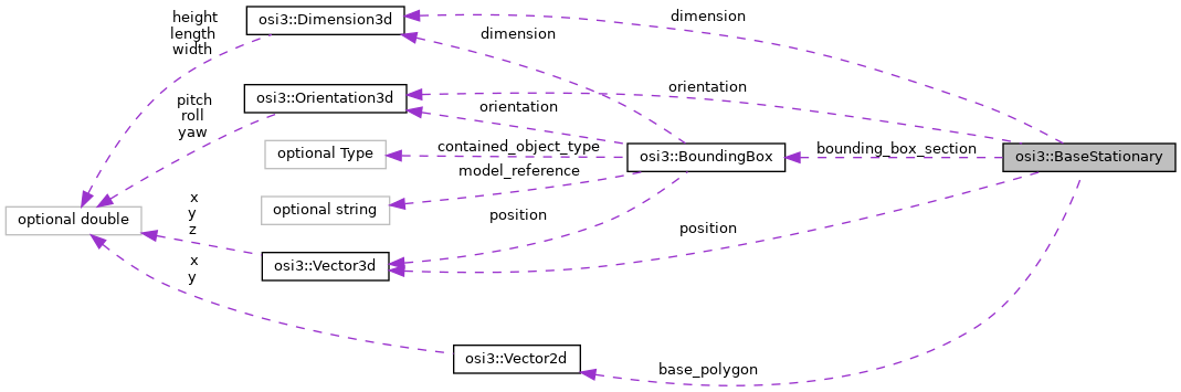
| optional Dimension3d | dimension = 1 |
| The 3D dimensions of the stationary object (bounding box), e.g. More... | |
| optional Vector3d | position = 2 |
| The reference point for position and orientation, i.e. More... | |
| optional Orientation3d | orientation = 3 |
| The relative orientation of the stationary object w.r.t. More... | |
| repeated Vector2d | base_polygon = 4 |
| Usage as ground truth: The two dimensional (flat) contour of the object. More... | |
| repeated BoundingBox | bounding_box_section = 5 |
Sub-divisions of the overall bounding box of the BaseStationary object. More... | |
Detailed Description
The base attributes of a stationary object or entity.
This includes the StationaryObject , TrafficSign , TrafficLight , RoadMarking messages.
All coordinates and orientations from ground truth objects are relative to the global ground truth frame (see image). (All coordinates and orientations from detected objects are relative to the host vehicle frame (see: Vehicle vehicle reference point).)
Member Data Documentation
◆ dimension
| optional Dimension3d osi3::BaseStationary::dimension = 1 |
The 3D dimensions of the stationary object (bounding box), e.g.
a landmark.
- Note
- The
dimensionmust completely enclose the geometry of theBaseStationary.
◆ position
| optional Vector3d osi3::BaseStationary::position = 2 |
The reference point for position and orientation, i.e.
the center (x,y,z) of the bounding box.
◆ orientation
| optional Orientation3d osi3::BaseStationary::orientation = 3 |
The relative orientation of the stationary object w.r.t.
its parent frame, noted in the parent frame. The orientation becomes global/absolute if the parent frame is inertial (all parent frames up to ground truth).
\( Origin_{\text{base stationary entity}} := Rotation_{yaw,pitch,roll}( \) orientation \( )* (Origin_{\text{parent coord system}} - \) position \( )\)
- Note
- There may be some constraints how to align the orientation w.r.t. to some stationary object's or entity's definition.
◆ base_polygon
| repeated Vector2d osi3::BaseStationary::base_polygon = 4 |
Usage as ground truth: The two dimensional (flat) contour of the object.
This is an extension of the concept of a bounding box as defined by Dimension3d. The contour is the projection of the object's outline onto the z-plane in the object frame (independent of its current position and orientation). The height is the same as the height of the bounding box.
Usage as sensor data: The polygon describes the visible part of the object's contour.
General definitions: The polygon is defined in the local object frame: x pointing forward and y to the left. The origin is the center of the bounding box. As ground truth, the polygon is closed by connecting the last with the first point. Therefore these two points must be different. The polygon must consist of at least three points. As sensor data, however, the polygon is open. The polygon is defined counter-clockwise.
◆ bounding_box_section
| repeated BoundingBox osi3::BaseStationary::bounding_box_section = 5 |
Sub-divisions of the overall bounding box of the BaseStationary object.
The bounding box sections can include separate parts on partially-opaque objects such as trees with a distinction between trunk and crown.
- Note
- The bounding box sub-divisions can extend beyond the overall bounding box, however no actual geometry must reside outside of the overall bounding box.
- If any sub-divisions are provided, then they must cover all occupied space of the overall bounding box. In other words, a consumer of this data is guaranteed that any part of the overall bounding box that is not covered by any sub-division is free of physical objects, and thus no collisions can occur there.
The documentation for this struct was generated from the following file:
- osi_common.proto